English
 Español
 简体中文
Aerospace injection molding exists because flight hardware punishes weight and rewards processes that repeat. Put plainly: for non-structural plastic parts such as cabin trim, air ducts, avionics enclosures, cable clamps and connector insulators, injection molding is the default manufacturing route, and the deciding factors are resin qualification and tooling quality rather than the molding itself. A component that passes flame, smoke and toxicity review, holds its dimensions across thousands of shots, and weighs 40 to 80 percent less than its machined metal counterpart is exactly what a bill of materials for an aircraft interior or equipment bay is looking for.
This guide sets out what the process actually makes, which resins survive aerospace review, the tolerances you can honestly commit to, and how to evaluate a mould manufacturer before money changes hands. The perspective throughout is practical: our team at Yuyao Hualong Moulds & Plastic Products Co., Ltd. has built moulds and molded parts for European and American brands since 1988, including aircraft accessories, instrument housings, sensor shells and electrical connectors, so the advice below reflects the factory floor rather than a brochure.
Bottom line: treat aerospace injection molding as a materials and tooling problem first; the resin certificate and the steel in the mould decide far more than the press schedule.
Content
- 1 What Aerospace Injection Molding Actually Makes
- 2 Why Injection Molding Wins for Flight-Weight Plastic Parts
- 3 Materials That Pass Aerospace Review: PEI, PEEK and PPS
- 4 Tolerance, Draft and Wall Rules That Decide Whether a Part Qualifies
- 5 Quality Systems, Traceability and the Paper Trail
- 6 From CAD Model to Batch Delivery: Working With a Mould Manufacturer
- 7 Care, Inspection and Service-Life Guidance for Molded Parts
- 8 Frequently Asked Questions About Aerospace Injection Molding
- 8.1 What tolerances can aerospace injection molding hold?
- 8.2 Which plastics are most common in aerospace injection molding?
- 8.3 Is injection molding suitable for prototype and low-volume aerospace parts?
- 8.4 How should I evaluate an injection molding manufacturer or supplier for this work?
- 8.5 What does FST compliance actually require?
- 9 Keep Exploring Hualong's Moulding Capabilities
What Aerospace Injection Molding Actually Makes
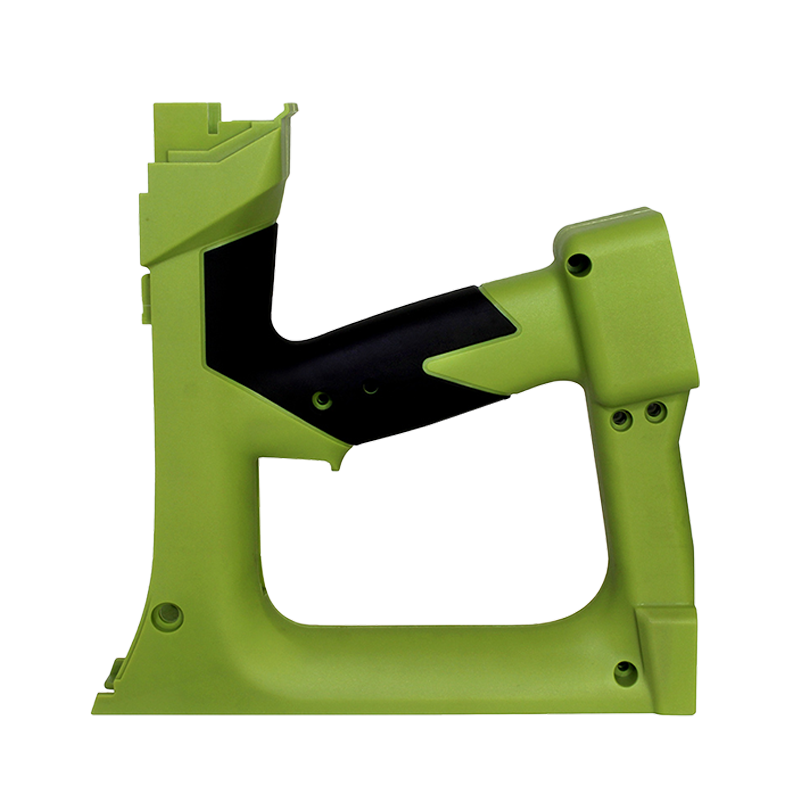
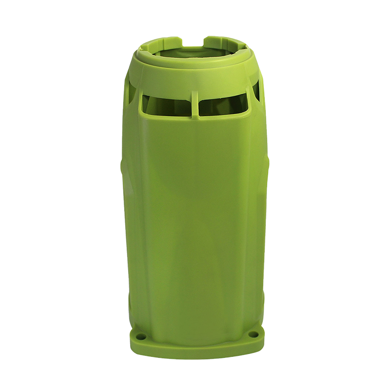
The fastest way to understand the process is to walk through an aircraft in your mind. Almost every plastic part you would pass is a candidate for injection molding, because the part is small to medium sized, needed in quantity, and required neither to bend nor to burn. Three families account for most of the work.
Cabin interior and air-management components
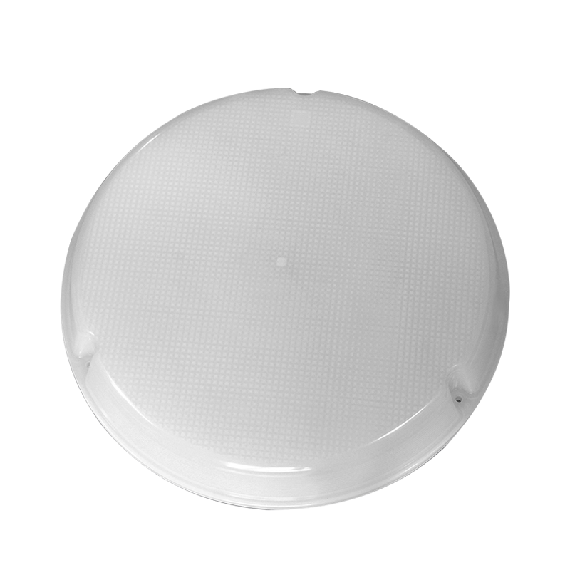
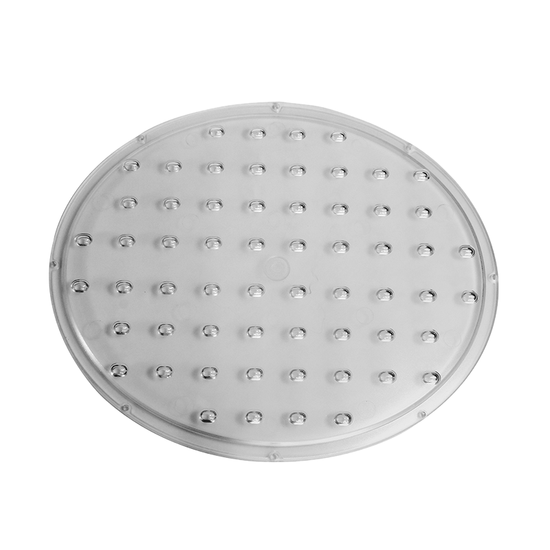
Cabin interiors are governed by flammability rules such as 14 CFR 25.853, which sets 12-second vertical burn, smoke density and toxicity limits for interior materials. Molded parts in this zone include air ducts and vents, lighting lenses and diffusers, seat side covers, armrest caps, galley fittings, trim panels and switch guards. Injection molding suits these parts because thin, flowing geometries that would be expensive to fabricate from sheet metal can be molded in one shot with inherently flame-retardant resins, and the surface finish is produced by the mould rather than by secondary painting.
Enclosures, bezels and instrument housings
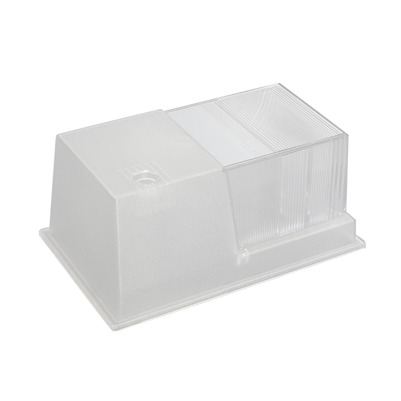
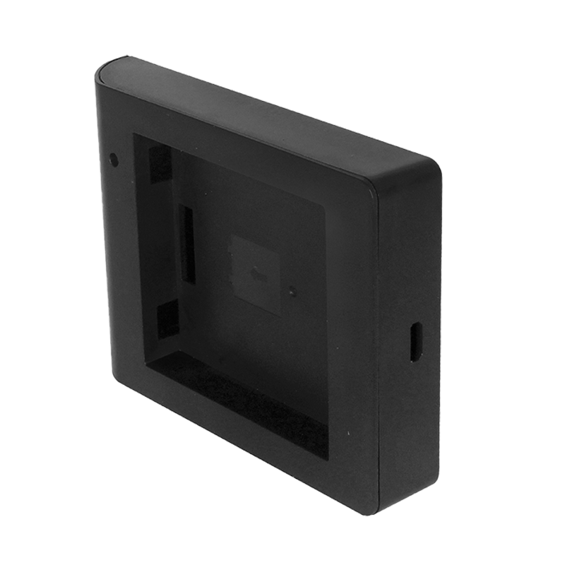
Equipment bays and cockpit side walls carry avionics boxes, sensor housings, control panels and display bezels, all of which want dimensionally stable, electrically insulating enclosures. Polyetherimide is a natural fit here: it is inherently flame resistant, holds its dimensions near heat sources, and molds with the crisp detail a bezel or lens frame needs. Our aircraft accessories line at Hualong grew from exactly this crossover, where the tooling discipline developed for industrial instrument and monitoring enclosures transfers directly to aviation-adjacent hardware.
Connectors, clamps and fastening hardware
The least glamorous parts keep the most aircraft grounded: cable clamps, grommets, connector insulators, battery holder shells, knobs and switch buttons. These components look trivial, but a cracked cable clamp or a deformed connector insulator creates chafing, intermittent faults and maintenance findings. Molding them in one shot, in a flame-rated resin, with consistent wall thickness around the insert is both cheaper and more repeatable than assembling a metal bracket with a separate insulator.
Cabin interior
Trim panels, seat hardware, armrest caps, galley fittings in FST-critical resins.Air management
Ducts, vents, diffusers and louvers molded thin-wall for minimum mass.Electronics
Avionics enclosures, display bezels, sensor and instrument housings.Hardware
Cable clamps, grommets, connector insulators, knobs and switch buttons.
Key point: none of these parts carries primary structural load, yet all of them carry qualification paperwork; that combination of low load and high documentation is where injection molding is unbeatable.
Why Injection Molding Wins for Flight-Weight Plastic Parts
Injection molding wins on three axes that matter in aviation: part cost at volume, shot-to-shot repeatability and freedom of geometry, all while removing mass. The process itself is simple to describe: dried resin pellets are melted inside a barrel, a screw injects the melt into a hardened steel mould under high pressure, the part is packed, cooled and ejected, and the cycle repeats every 20 to 80 seconds depending on wall thickness. That cycle, repeated unattended, is what makes the economics irresistible once a programme passes a few hundred units.
Choosing between injection molding and CNC machining is less about which process is universally better and more about which axis of performance your programme values most. The radar chart below scores the two routes across five dimensions that matter for aerospace-adjacent plastic hardware. Each axis runs from 0 to 100 as a relative, experience-based rating rather than an absolute measurement. The dark blue polygon represents injection molding, while the lighter polygon represents machining the same designs from block material. The shape of each polygon tells you where each process earns its keep.
Injection moldingCNC machining
The two polygons overlap far less than most buyers expect, and that gap is the whole business case. On the volume-cost axis, injection molding scores near the top because once the tool is paid for, each additional part costs cents rather than machine-hours. Machining sits at the bottom of the same axis for the mirror-image reason: every part pays the full cutting time again. On low-volume affordability the relationship flips, which is why a score of 35 appears for molding on that axis. A production tool in pre-hardened steel represents weeks of machining and a five-figure investment before the first part exists. Machining needs no tool at all, so for ten units, fifty units or a single flight-test article, it remains the rational choice.
The repeatability axis favors molding because a maintained cavity produces part number 50,000 with the same dimensions as part number 50, within the shrinkage behavior of the resin. On geometric complexity, molding again leads: ribs, bosses, snap features, living hinges and consolidated multi-function housings are formed in one shot, while machined parts force assembly steps and fasteners. Thin-wall capability underlines the weight argument, since molded walls of 1.5 to 2.0 mm are routine, whereas machined walls at that gauge demand slow, fragile cutting. The practical procurement conclusion is a hybrid strategy: machine the first articles and qualification samples, cut the production tool in parallel, and let the two polygons hand over to each other at the crossover volume. For most aerospace-adjacent programmes that crossover lands somewhere between several hundred and a few thousand units, which is precisely the quantity band where cabin refits, sensor retrofits and equipment upgrades live.
Conclusion: machine the qualification samples, mold the production run, and let the crossover volume, not habit, make the decision.
Materials That Pass Aerospace Review: PEI, PEEK and PPS
Resin selection is where aerospace injection molding separates from consumer work. Interior and equipment-bay materials must satisfy flame, smoke and toxicity requirements, which in practice means UL94 V-0 behavior at the specified wall thickness, compliance with the burn and smoke criteria of 14 CFR 25.853 for cabin applications, and, for space-adjacent hardware, low outgassing per ASTM E595 with total mass loss below 1.0 percent and collected volatile condensable materials below 0.1 percent. Add moisture, coolant and hydraulic-fluid exposure, and the list of realistic candidates shrinks to a handful of engineering resins.
Weight is the currency of aerospace engineering, and every resin choice is a trade between mass, temperature resistance and cost. The chart below compares the densities of the four workhorse injection molding resins against the three metals they most often replace. All figures are typical values for unfilled grades, expressed in grams per cubic centimeter. Blue bars represent engineering polymers, while the darker bars represent aluminum, titanium and stainless steel. Even a quick glance shows why programme engineers keep reaching for molded plastics on brackets, ducting and housings.
| ABS | |
| PEI | |
| PEEK | |
| PPS | |
| Aluminum 6061 | |
| Titanium Ti-6Al-4V | |
| Stainless steel 316 |
The chart makes the mass case in one glance: PEI at 1.27 grams per cubic centimeter weighs less than half of an identical volume of aluminum at 2.70. Against titanium the gap widens to roughly 71 percent, and against stainless steel the molded part removes about 84 percent of the mass outright. Those percentages translate directly into fuel burn over an airframe's service life, which is why lightweighting programmes keep pulling plastic parts out of metal drawings. Density alone, however, is not the whole decision, because stiffness and strength per gram are what actually matter. Glass-filled grades close much of that gap: 30 percent glass-reinforced PEI or PPS raises stiffness dramatically while pushing density up only to roughly 1.5, still far below aluminum.
Note also that the polymer bars sit close together, which means the resin choice can be driven by temperature, flammability and chemical requirements rather than by weight penalties. Choosing PEEK over PEI for a bracket costs multiples in resin price but adds almost nothing to the mass budget. Metals keep the advantage where temperatures exceed polymer limits, where electromagnetic shielding is required, or where a threaded metal insert must carry repeated loads. Shielding, incidentally, can often be recovered with conductive coatings applied to molded enclosures. Part consolidation compounds the effect, because one molded housing replaces several machined pieces along with their fasteners. The correct reading of the chart is therefore not that plastic always wins, but that for every metal part in the 150 to 200 degree Celsius service band there is usually a resin that removes 40 to 80 percent of its weight.
Resins you will actually be quoted
Four resin families cover the overwhelming majority of aerospace molding requests, and their trade-offs are summarized below. Treat the heat figures as continuous-service guidance rather than absolute limits, and always qualify the exact grade, color and additive package you intend to fly.
| Resin | Heat capability | Flammability | Typical uses |
|---|---|---|---|
| PEI | About 170 degrees Celsius continuous use, glass transition at 217 | Inherent V-0 behavior, low smoke | Avionics enclosures, bezels, interior trim, light-diffusing covers |
| PEEK | About 250 degrees Celsius continuous use, melting point 343 | V-0, very low smoke and toxicity | High-temperature ducting, bushings, clips near heat sources |
| PPS | About 200 degrees Celsius continuous use | V-0, outstanding chemical resistance | Connector bodies, sensor housings, fuel-system-adjacent fittings |
| FR PC/ABS | About 80 to 105 degrees Celsius continuous use | Flame-retarded grades, FST variants | Cost-driven interior shrouds and covers |
What the datasheet must prove
Aerospace buyers should expect documentation, not adjectives. Ask for the UL recognition or equivalent flammability report tied to the exact grade and wall thickness, lot traceability from pellet bag to molded part, drying records before molding, and outgassing data where the application calls for it. A supplier who cannot produce these papers quickly is telling you something important about how the rest of the programme will run.
Bottom line: in aerospace molding the resin choice is roughly 80 percent of the risk; lock the grade, the colorant and the documentation before the steel is cut.
Tolerance, Draft and Wall Rules That Decide Whether a Part Qualifies
Honest numbers first: a well-built mould in a controlled process holds plus or minus 0.1 mm on most dimensions without effort, plus or minus 0.05 mm routinely with steel cavities and disciplined machine parameters, and plus or minus 0.025 mm on small, stable features when cavity-pressure control and careful measurement are added. Anything tighter should be treated as a special case requiring a datum strategy, gauge capability and often post-mold measurement 24 to 48 hours after molding, because resins continue to shrink slightly as they equilibrate.
| Specify this at the design stage | What goes wrong if you skip it |
|---|---|
| Uniform walls of 1.5 to 3.0 mm, with ribs at 50 to 60 percent of the adjoining wall | Sink marks, voids, warpage and cycle times that double |
| 1 to 2 degrees of draft on every side wall | Scuffed textures, ejection damage and cosmetic scrap |
| A GD&T datum scheme that tolerances only functional features | Toolmakers chase impossible numbers and every dimension costs more |
| Metal-safe tooling: plan to remove steel, never to add it | Weld-line relocations that force a new cavity insert |
| Gate location agreed against fill simulation | Weld lines, gas traps and warp exactly where you cannot accept them |
| Mould temperature and venting plans matched to each resin family | Short shots, brittle weld lines and dimensional drift between cavities |
Where tight tolerances get lost
Tolerances are usually lost in four places: moisture, heat, balance and measurement. Resins that absorb water must be dried to specification before molding or the melt sputters and dimensions wander. Unbalanced cavity filling pushes one cavity into tolerance and another out. Glass-filled resins shrink differently along and across the flow direction, so features must be toleranced with that anisotropy in mind. Parts measured warm will pass dimensions that fail cold, which is why the measurement environment belongs in the drawing notes. For enclosure-type parts, annealing semi-crystalline resins such as PEEK after molding can stabilize dimensions before final inspection. For a worked example of disciplined enclosure molding, the instrument housing programmes we run at Hualong apply exactly these rules to housings that must seal, mount and carry connectors without drift.
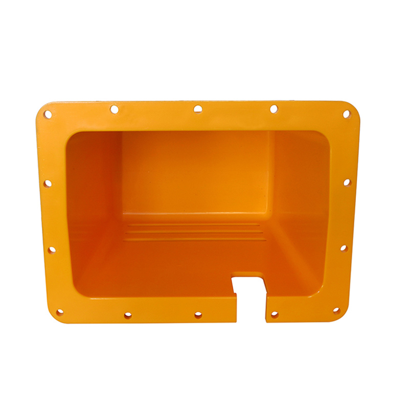 Custom Injection Molded Instrument HousingA precision-molded enclosure built to hold sealing, mounting and connector features within tolerance. It illustrates the drying, filling balance and measurement practices discussed for dimensionally stable housings.View Product →
Key point: specify tolerances on what actually functions and give the mould maker datum freedom everywhere else; over-toleranced drawings are the most expensive document in the whole programme.
Quality Systems, Traceability and the Paper Trail
Aerospace procurement is documentation with parts attached. First article inspection per AS9102, ballooned drawings and dimensional reports establish that the tool produces conforming parts. Material certificates and lot traceability establish that every bag of resin can be followed from receipt to the cavity and shot that used it. Per-shot process logging establishes that the parameters approved at qualification are still the parameters running months later. Molded parts should carry cavity and date markings where the drawing allows, so any field finding can be traced to a specific tool position and production day.
Many aerospace-adjacent parts are purchased through tier-one and tier-two integrators who carry the programme certifications, but the mould maker underneath still needs the discipline. During a supplier audit, count machines and inspection equipment with your own eyes, ask who cuts the steel in-house, review a sample first-article package, and ask how corrective actions are logged. At Hualong, for example, more than 20 machining centres build the moulds on site and more than 20 inspection devices support dimensional verification, which means tolerance disputes are settled between our toolroom and our quality team rather than between two different companies.
Conclusion: audit the paper trail as seriously as the parts; in aviation, a dimension without a record does not exist.
From CAD Model to Batch Delivery: Working With a Mould Manufacturer
A one-stop workflow compresses risk because a single team owns the part from drawing review to assembly. In practice it runs like this: design-for-molding feedback on your CAD model, mould design with steel selection matched to resin and volume, trial shots with dimensional reports, sample approval, then pilot and production batches on the machines that ran the trials. Every handoff you remove is a place where a tolerance, a resin grade or an inspection record used to get lost.
Scale matters as well as structure. Hualong was founded in 1988 in Yuyao, Zhejiang, operates a 9,000 square metre site with more than 8,000 square metres of workshops, and runs 15 injection machines with shot weights from 100 g to 3,500 g, which covers everything from a connector insulator to a substantial equipment housing. More than 30 technical and management staff support a one-stop flow of product development, mould design and manufacture, injection molding and final assembly, and the factory serves European and American brands that audit hard and reorder often.
The small parts show the discipline best. A connector insulator or battery holder shell demands a flame-rated resin, tight wall control around metal inserts and consistent dimensions across millions of shots, which is precisely the combination a flight-adjacent programme needs from its custom injection molding supplier.
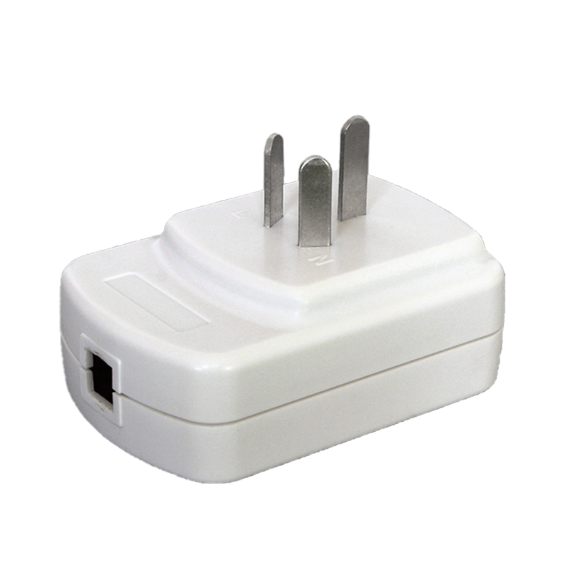
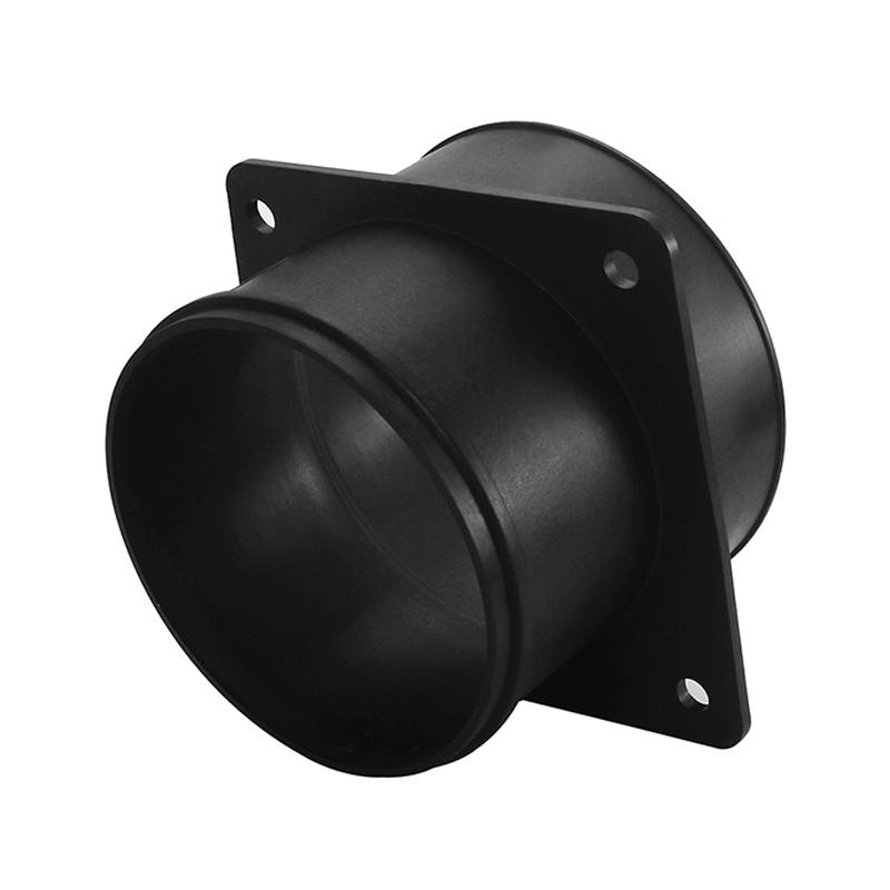 Custom Injection Molded Connector InsulatorA small flame-rated molded part with tight wall control around metal inserts and consistent dimensions over long production runs, showing the small-part molding discipline the article highlights.View Product →
Bottom line: choose a mould manufacturer that builds its own steel, molds its own trials and inspects with its own equipment; ownership of the whole chain is what protects your tolerances.
Care, Inspection and Service-Life Guidance for Molded Parts
Molded parts rarely fail suddenly; they fade. Ultraviolet exposure embrittles unprotected surfaces, sustained bolt load makes plastics creep, aggressive solvents craze amorphous resins, and repeated over-torque rounds out self-tapping bosses. A short, scheduled inspection routine catches all four failure modes long before they become findings.
- Clean with mild detergent and water; keep unapproved solvents away from amorphous resins such as PEI and PC/ABS to prevent stress crazing.
- Inspect bosses, insert areas and clamp radii for micro-cracks at every scheduled maintenance window.
- Re-torque fasteners to the drawing value with a calibrated tool, not by feel.
- Store spares in UV-protected packaging, away from heaters and direct sunlight.
- Replace, rather than adhesive-repair, any cracked bracket or clamp that supports equipment.
- Re-verify critical dimensions after any re-molding, annealing or re-finishing step.
For service-life planning, remember that thermoplastics creep under sustained load, so a bracket that passes a static test at room temperature may relax over years under combined load and elevated temperature. Reputable suppliers design de-rating into the part; maintenance teams should respect it by resisting improvised loads, additional cable bundles or relocated equipment on molded brackets.
Key point: most molded-part failures in service are load, solvent or UV stories; all three are preventable with routine inspection and disciplined handling.
Frequently Asked Questions About Aerospace Injection Molding
The questions below are the ones procurement teams and design engineers actually raise when a programme first touches molded flight-adjacent hardware.
Remember: if a question is not answered by documentation, it will eventually be answered by a field finding; always choose the documentation.
Keep Exploring Hualong's Moulding Capabilities
Rather than scattering links through the text above, we have gathered the two most useful next steps into one place: the service model behind our one-stop workflow, and the product family where our aircraft accessories and instrument housings live.
Our one-stop service model: from product development to assembly
How a single team owns design feedback, mould making, molding and assembly, and why that shortens the path from CAD model to approved batches.Instrument and device shell product range
Browse aircraft accessories, instrument housings, detection accessories and electrical fittings molded and assembled at Hualong.
Next step: send your drawing and resin requirement to the team that cuts the steel; an early DFM conversation is the cheapest tolerance insurance available.