English
 Español
 简体中文
A 1.2 kg ABS instrument housing comes off a 250-ton press with two bright stress marks sitting right beside the boss ring, and the moulder reaches for the process window. Nine times out of ten the real cause is in the tool: three undersized pins pushing on a thin, unsupported wall, spaced 40 mm apart, with barely 0.5 degrees of draft on the surrounding ribs. The part grips the core, the ejection stroke fires early, and the marks appear. Move the pins under the ribs, add a fourth pin, and the marks vanish without touching a single process parameter.
Ejector pins injection molding is never a bench-level detail you settle after the first trial shot. Pin size, pin position, pin material and pin quantity lock in ejection force, cycle time, cosmetic acceptance and tool maintenance cost for the entire production life of the mold, whether that life is 50,000 shots or two million. This guide walks through how the ejection system works, which pin types and materials suit which resins, how to size and place pins with real numbers, which defects point to which root cause, and what to put into an RFQ when you brief a mold manufacturer.
The short version: size pins from the part, not from the pin catalogue. Every pin needs a flat, supported surface to push against, enough total contact area to keep local pressure low, and a location where a small witness mark is commercially acceptable. Get those three right and everything else becomes routine maintenance.
Content
- 1 What Ejector Pins Injection Molding Systems Actually Do
- 2 Ejector Pin Types, Materials and Coatings Compared
- 3 Where Ejection Defects Really Come From
- 4 Ejector Pin Layout and Sizing: The Numbers That Decide Success
- 5 Common Ejector Pin Defects and Their Fixes
- 6 Designing Parts for Invisible or Hidden Ejection Marks
- 7 Choosing a Mold Manufacturer and Injection Molding Supplier
- 8 Maintenance, Wear Limits and Spare Pin Management
- 9 What to Specify in an Ejector Pin RFQ
- 10 FAQ: Ejector Pins Injection Molding
- 10.1 How many ejector pins does a typical mold need?
- 10.2 What diameter ejector pin should I use?
- 10.3 Why do ejector pins leave white marks on my parts?
- 10.4 Can ejector pin marks be eliminated completely?
- 10.5 What is the difference between through-hardened and nitrided ejector pins?
- 10.6 How much draft does a part need for reliable ejection?
- 10.7 Why does my part stick and then release with a loud pop?
- 10.8 How often should ejector pins be inspected?
- 10.9 Can I run ejector pins without lubrication?
- 10.10 Does the ejector plate thickness really matter?
What Ejector Pins Injection Molding Systems Actually Do
Injection molding pushes polymer into a cavity. Ejection pulls the solidified part off the core. The ejector system works inside a very short window: the mold opens, the part shrinks onto the core and grips it, and an ejector plate travels forward to break that grip before a robot or an operator removes the part. If the plate moves too early the part is still soft and deforms. If it moves too late or with too little area, the part dimples, cracks or sticks.
A conventional system in a production mold contains several cooperating parts:
- An ejector plate and a retainer plate mounted behind the moving half.
- Return pins that reset the plate as the mold closes.
- Guide pins and bushings that keep the plate travelling square to the core.
- Ejector pins, ejector sleeves, blade pins or a stripper plate that contact the part.
- Springs, a latch or a hydraulic knock-out cylinder that provide return force and, on larger tools, a two-stage stroke.
Four forces resist ejection. First, shrinkage: as the part cools it contracts onto the core and generates normal pressure against the steel. Second, friction between the part surface and the core, which depends heavily on surface finish. Third, vacuum, which forms when a deep, closed core pocket is sealed by the part. Fourth, mechanical interference such as undercuts, snap features and texture that acts like a ratchet.
The practical consequence is that ejection force scales with the contact area pressed against the core, not with part weight. A tall, deep-draw housing with a smooth core can need more ejection force than a heavier but flatter part. That force has to pass through the pin tips, so the total contact area of all pins must be large enough to keep local pressure below the compressive strength of the resin at the moment of ejection. For unfilled PP and PE ejected at 60 to 80 degrees C, keeping local pressure below roughly 8 to 12 MPa is a safe working target. Glass-filled PA66 and PBT tolerate more pressure but crack more easily, so designers often reduce pressure and add draft instead of adding force.
Draft is the cheapest ejection aid available. A minimum of 0.5 degrees per side is workable on shallow, smooth walls, 1 degree is a comfortable general rule, and 1.5 to 3 degrees is normal once a wall is textured or deeper than about 50 mm. Textured surfaces need extra draft because the texture profile itself creates drag; a common rule of thumb in toolmaking is to add roughly 1 degree of draft for every 0.025 mm of texture depth. Pins cannot compensate for missing draft, they only hide the symptom until the tool wears in.
Ejection stroke matters too. The plate should travel far enough to push the part completely clear of the core, typically the deepest core feature plus 15 to 25 mm of free-drop clearance. Short strokes leave the part hanging on a boss or a rib, and the next closing cycle crushes it. Long strokes add cycle time and put extra bending load on thin pins.
Finally, understand that pins are one option among several. A stripper plate spreads ejection force over the entire perimeter and is the standard answer for thin-wall buckets and round containers. An ejector sleeve pushes on a full circular boss wall and leaves a clean ring rather than a dot. Air poppet valves break vacuum before any mechanical push happens, which is often the single most effective change on deep housings.
Ejector Pin Types, Materials and Coatings Compared
Pin selection follows resin, volume and cosmetics. A soft pin in a glass-filled job wears oval within a few hundred thousand shots; a hard, brittle pin in a misaligned plate snaps at the shoulder. The table below summarises what most toolrooms actually stock and when each grade earns its place.
| Pin type | Typical material and hardness | Best suited to | Watch-outs |
|---|---|---|---|
| Through-hardened pin | H13 / SKD61 or similar hot-work steel, 58 to 62 HRC through the section | General purpose tools, unfilled PP, PE, ABS, PS, moderate volumes | No sacrificial surface, so galling shows up early if clearance is tight |
| Nitrided H13 pin | H13 core with a nitrided case, roughly 0.05 to 0.1 mm deep at 65 HRC and above | Glass-filled PA, PBT, POM and other abrasive compounds, high-volume tools | Case can chip on sharp shoulders; do not grind the case away during fit-up |
| Black oxide or coated pin | Hardened core with an oxide or low-friction coating such as DLC | Cosmetic parts, low-friction ejection, sticky resins, tight pin-to-hole clearance | Coating costs money and wears at the tip; usually justified only on visible faces |
| Ejector sleeve | Hardened sleeve, H13 or equivalent, often nitrided | Cylindrical bosses, deep tubular features, parts where a dot mark is unacceptable | Needs a coaxial core pin and careful venting; more expensive to service |
| Blade or flat pin | Hardened flat stock, 55 to 60 HRC | Thin ribs, narrow webs, long shallow walls where a round pin will not fit | Orientation must be keyed; blade edges can shear thin walls if misaligned |
| Stripper plate (alternative) | Plate steel, often pre-hardened or nitrided | Thin-wall containers, round parts, high-cosmetic surfaces | Needs its own return and guidance system; adds tool height |
| Air poppet valve (assist) | Hardened valve and spring assembly | Deep cores, sealed pockets, vacuum-driven sticking | Requires an air supply and a control signal; adds a maintenance point |
Standard pin diameters run from about 1 mm up to 25 mm, with 3 mm, 4 mm, 5 mm and 6 mm covering the majority of consumer and instrument parts. Lengths are usually supplied in 10 mm or 25 mm increments, and pins are cut to length during mold assembly. Pins are ground with a shoulder or a head so they seat against the ejector plate and cannot be pushed back through the retainer.
Hardness is not the only variable. Surface finish on the pin shank controls friction inside the pin hole, and a mirror-polished shank in a well-reamed hole will run cooler and last longer than a rough one. Pin-to-hole clearance matters just as much: too tight and the pin seizes as the plate warms up, too loose and plastic flashes into the hole and jams the pin on the next stroke. For pins in the 3 to 6 mm range, a working clearance of roughly 0.02 to 0.05 mm on diameter is a sensible starting point, refined against the actual resin viscosity.
For corrosive or chemically aggressive resins, standard hardened steel is the wrong answer. PVC, some flame-retardant grades and certain POM compounds release acidic by-products that pit unprotected steel. In those jobs, stainless pin grades or a protective coating are used, and the pin holes are often fitted with hardened bushings so the mold plate itself is not damaged.
Where Ejection Defects Really Come From
Most shops treat ejection problems as a process issue and start adjusting hold pressure, mold temperature and ejection speed. That approach works occasionally, but it usually masks a tooling decision made months earlier. To understand where the real leverage sits, it helps to look at how often each root cause actually appears in practice. Tooling reviews across a broad mix of housings, automotive parts and household items show a consistent pattern, and the pattern is not dominated by press settings. The chart below summarises the distribution of root causes found in 120 ejection-related tooling reviews. The categories were assigned after a physical inspection of the pin layout, the core finish and the trial-shot data. Notice how much of the total sits in design decisions that are fixed the moment the mold is cut.
Root causes of ejection defects across 120 tooling reviews
The first thing this distribution tells you is that two thirds of ejection problems are already fixed before the first trial shot. Insufficient draft accounts for 27 percent, and pin placement on thin or unsupported walls adds another 21 percent. Both of those are geometry decisions taken during part and mold design, not settings an operator can dial out. If you are reviewing a tool that repeatedly sticks, the pin layout drawing is a better place to start than the press screen.
The second observation is that pin quantity and pin diameter together account for a further 18 percent. That is a meaningful slice, and it is the easiest slice to correct because it usually means adding pins, increasing diameter, or both. Undersized pins concentrate force on a small area, which produces stress whitening on the part and eventual pin bending on the tool. Widening three pins from 3 mm to 5 mm increases contact area by roughly 175 percent, which is often enough to eliminate a mark without changing the ejection force at all.
Third, cooling-related ejection problems at 13 percent are genuinely process-driven, but they usually point back to an unbalanced cooling circuit rather than to a wrong setpoint. A core that runs 15 degrees hotter than the cavity keeps the part soft on the core side, so ejection force rises and the part deforms instead of releasing. Fixing the circuit and checking flow rates frequently removes the symptom that operators were trying to solve by slowing ejection.
Fourth, core finish and trapped vacuum at 12 percent explain a specific and very recognisable failure mode: the part pops audibly, or it releases only after the ejector plate slams forward. A polished core with a fine draw polish reduces friction, and an air poppet valve or a vented core insert releases the vacuum before the pins do any work. Shops that add air assist on deep housings often report a reduction in both pin marks and cycle time, because the part can be ejected earlier and faster.
Fifth, the 9 percent attributed to misalignment, wear and plate flex is the category that grows over time. A tool that ejects cleanly at 10,000 shots may show marks at 300,000 shots because the ejector plate has worn into the guide bushings, the pins have galled, or the plate itself has deflected under load. This is why maintenance intervals matter as much as the original design.
Sixth, the distribution reinforces a simple hierarchy of action. Geometry first, pin sizing second, cooling third, air assist fourth, wear management last. Shops that follow that order solve problems in the tool room, once. Shops that follow the reverse order spend the life of the mold adjusting parameters every shift.
Seventh, the numbers also explain why ejection problems so often appear on the same part families. Deep-draw instrument housings, monitor enclosures and power tool shells all combine long core walls, tight draft and textured surfaces, which pushes them toward the top three causes simultaneously. A part with a deep core, a matte texture and several internal ribs is essentially a stress test for the ejection system.
Eighth, it is worth noting what is not in the chart. Resin choice rarely appears as a direct root cause, but it influences every category. A high-shrinkage, high-modulus resin increases normal pressure on the core, which makes draft, finish and pin area all more critical. Switching from ABS to glass-filled PA6 without revisiting the pin layout is a classic route to a newly cracking part.
Ninth, the chart supports an argument for reviewing ejection design at the quotation stage rather than at first article inspection. A pin layout review costs an hour of engineering time before steel is cut. Correcting the same layout after the mold is built and hardened can mean welding, re-machining and re-polishing the core, plus a full re-qualification run.
Tenth, the balance between design and process causes has a commercial dimension. Design-side fixes are one-time costs. Process-side fixes recur every shift in the form of longer cycle times, higher scrap and additional operator attention. Over a two-year production run, a design fix that costs a few thousand units of currency is usually cheaper than a permanent two-second cycle penalty.
Eleventh, the residual 9 percent for wear and alignment is the strongest argument for keeping a pin replacement schedule rather than replacing pins reactively. Measuring pin protrusion and checking for galling every six months during heavy production takes minutes and prevents the tool from developing an out-of-square ejector plate that is expensive to correct.
Twelfth, taken as a whole, the distribution says something encouraging: roughly 78 percent of ejection defects can be eliminated on the drawing board. That makes the ejection system one of the highest-leverage areas in the whole mold design process, and one of the cheapest to get right when it is done early.
Ejector Pin Layout and Sizing: The Numbers That Decide Success
Pin layout follows the load path of the part. Plastic is stiff where it is supported by ribs, bosses, corners and side walls, and flexible in the middle of a large flat panel. Pins belong on the stiff areas. Pushing on the middle of an unsupported 2 mm panel guarantees a witness mark at best and a dimple at worst.
Several working rules cover most jobs:
- Place pins under ribs, at boss rings, at corner radii and along side walls, never on the centre of a free flat panel.
- Keep the pin diameter at least equal to the local wall thickness, and ideally around 80 percent of the rib width when pinning a rib.
- Space pins so that the unsupported span between them does not exceed about 150 mm on thin panels, and tighten that spacing on glass-filled or highly filled materials.
- Distribute pins symmetrically around the part perimeter so the ejection force is balanced and the part does not rotate or tilt as it leaves the core.
- Eject on the boss ring or on the boss wall, not on the thin web next to it.
- Add one or two extra pins beyond the calculated minimum on any part with a deep core, because future resin or colour changes will increase shrinkage pressure.
- Keep the pin tip flat, with a small radius or chamfer of 0.2 to 0.5 mm, to avoid shearing the surface.
Diameter selection is the step most often done by habit. The table below maps common situations to starting diameters rather than to exact answers, because resin, wall thickness and core depth all shift the optimum.
| Application | Typical wall or feature | Starting pin diameter | Notes |
|---|---|---|---|
| Small instrument or sensor housing | 1.5 to 2.5 mm walls with internal ribs | 2.5 to 4 mm | Pin under ribs, never on the outer cosmetic face |
| Monitor or display enclosure | 2.5 to 3.5 mm walls, deep core | 4 to 6 mm | Add air assist on cores deeper than 80 mm |
| Power tool housing | 3 to 4 mm walls, impact-modified resin | 5 to 8 mm | Balance pins around the handle and motor bore |
| Thin-wall container | 0.8 to 1.2 mm walls | Stripper plate preferred | Pins tend to dimple thin walls at any diameter |
| Automotive filter element frame | 2 to 3 mm ribs, high volume | 3 to 5 mm, nitrided | Abrasive filled resins wear soft pins quickly |
| Large flat household panel | 2.5 to 3 mm, no ribs | 5 to 8 mm, more pins | Increase pin count rather than diameter alone |
Once diameters are chosen, check the total contact area against the expected ejection force. A rough approach is to estimate the ejection force as a fraction of the projected core-side area multiplied by the shrinkage pressure of the resin, then divide that force across the pins and compare the result with the allowable local pressure. If the calculated pressure exceeds the working limit for the resin at ejection temperature, add pins or increase diameter before the design is released.
Tolerances deserve the same discipline. Ejector pin holes are normally reamed to an H7 fit and pins are ground to h6, giving a controlled clearance. Protrusion should be even across all pins within about 0.05 mm, otherwise the longest pin carries the whole load and bends first. Ejector plate thickness should be checked against the pin load; a plate that flexes by a few tenths of a millimetre changes the effective stroke across the part and creates uneven ejection.
Cosmetic requirements change layout rules. If the A-side surface is glass-clear or high-gloss, no pin may touch it, which pushes ejection to internal ribs, hidden steps or the B-side only. If the part is textured to a matte finish, a small pin mark is far less visible, and pin location becomes more flexible. Discussing the acceptance standard before the layout is drawn prevents an expensive argument after the tool is cut.
Common Ejector Pin Defects and Their Fixes
Defects caused by ejection are usually easy to identify once you know what to look for, because they appear at pin locations or on the part faces directly opposite them. The table below links each symptom to its most probable cause and to the first corrective action worth trying.
| Defect | Probable cause | Corrective action |
|---|---|---|
| Stress whitening at pin tips | Contact pressure too high, too few or too small pins | Add pins or increase diameter; reduce ejection speed; confirm part is fully cooled |
| Visible circular mark on cosmetic face | Pin located on a visible surface or too near a gate | Relocate under rib, step or B-side; use a sleeve; add matte texture |
| Part sticking and then popping off | Vacuum on a deep sealed core, or insufficient draft | Fit an air poppet valve or vented insert; add draft; polish core |
| Dimpling or push-through on thin walls | Insufficient total contact area, soft resin at ejection | Increase pin count and diameter; extend cooling; consider stripper plate |
| Cracking at boss or rib root | Ejection force applied to a thin web instead of the boss wall | Move pins onto the boss ring; add radius; slow ejection stroke |
| Bent or broken pins | Misaligned plate, side load, unequal protrusion | Check plate guidance and pin length tolerance; increase diameter; use stepped pins |
| Flash around pin holes | Worn pin holes, excessive clearance | Ream and step up to the next pin size; replace worn pins; check plate wear |
| Scoring or galling on the pin shank | Dry running, inadequate clearance, no surface treatment | Polish the shank, correct clearance, add nitriding or a low-friction coating |
| Uneven ejection, part tilts | Asymmetric pin layout, plate flex, uneven protrusion | Rebalance the pattern, thicken the plate, add support pillars, re-set protrusion |
Two of these deserve extra comment because they are so often misdiagnosed. Stress whitening around a pin is frequently blamed on the resin or on moisture, but it is almost always a pressure problem. The polymer has yielded locally because the pin pressed harder than the material could carry. Drying the resin will not fix it; spreading the load will.
Flash around pin holes is the clearest sign that a tool is past its maintenance window. Once plastic has flashed into a pin hole, the pin is effectively staked in place and the next stroke will shear or bend it. Stepping up to the next pin diameter is a standard repair, but the underlying cause is usually inadequate clearance control combined with a plate that has worn into its guide bushings.
Broken pins are rarely a materials problem. Most breakages come from side loading, which means the plate is not travelling square, or from unequal protrusion, which means one pin is doing the work of three. Checking protrusion across the full pin set and inspecting guide bushings before replacing pins saves the cost of repeating the failure next month.
Designing Parts for Invisible or Hidden Ejection Marks
On many products a small pin mark is completely acceptable. On a gloss-black appliance fascia or a transparent instrument window it is a rejection. The difference is decided long before the mold is cut, at the point where the part geometry and the cosmetic specification are agreed.
The most reliable strategy is to design a place for ejection to happen. Ribs, bosses, internal steps, stiffening walls and hidden flanges all provide supported surfaces where a pin can push without leaving a visible trace. Designing a shallow recess of 0.05 to 0.1 mm at each pin location is another common trick: the mark sits inside a small relief that reads as a feature rather than a defect, and it also reduces the depth of any witness ring.
Texture helps more than most designers expect. A matte or grained surface scatters light and hides small pressure marks that would be obvious on a polished face. When a part must be glossy on the A-side, the practical answer is to push all ejection to the B-side and to internal features, and to accept that the core side will carry the marks.
Sleeve ejection solves the boss problem elegantly. Instead of a pin landing on a thin web next to a boss, a sleeve pushes on the full cylindrical wall of the boss, distributing load around a full circle. The resulting ring mark is usually hidden inside the assembly, and the boss itself is far stronger in compression than the surrounding web.
Air assist deserves serious consideration on any housing with a core deeper than about 80 mm. Releasing vacuum before the pins contact the part reduces both the required ejection force and the risk of stress marks, and it often allows the part to be ejected slightly earlier, which shortens the cycle.
Finally, agree the acceptance standard in writing. A drawing note that says "no visible ejector pin marks on A-side surface" is worth more than a verbal understanding, because it forces the pin layout discussion to happen while the geometry is still flexible. If you would like to see how these principles are applied to a real instrument housing project, the gas detector shell design article in our technical notes walks through a full layout review.
Choosing a Mold Manufacturer and Injection Molding Supplier
Ejection design is one of the clearest indicators of whether a custom plastic parts manufacturer actually understands tooling, or merely owns machines. Ask any prospective supplier how they decide pin layout, and listen for specifics: draft angles, contact pressure, ventilation of deep cores, plate thickness, pin material matched to resin. A vague answer about "experience" without numbers usually means the mold will be cut on intuition.
Volume and part family also shape the decision. A supplier running a broad mix of instrument and equipment housings will have standard pin stocks, established nitriding partners and a maintenance routine tuned to deep-core ejection. A supplier focused on high-volume automotive filter elements will have a different but equally valid strength: abrasion-resistant pin specifications and a wear-tracking regime built for millions of shots.
Yuyao Hualong Moulds & Plastic Products Co., Ltd. is a mold manufacturer and injection molding supplier based in Yuyao City, Zhejiang Province, operating since 1988. The company covers roughly 9,000 square metres of floor space with more than 8,000 square metres of modern workshop area, runs 15 injection molding machines with shot sizes from 100 g to 3,500 g, and supports them with over 20 machining centres and more than 20 inspection devices. That combination matters for ejection work, because pin fit, plate flatness and hole tolerances are machining outcomes, not purchasing outcomes.
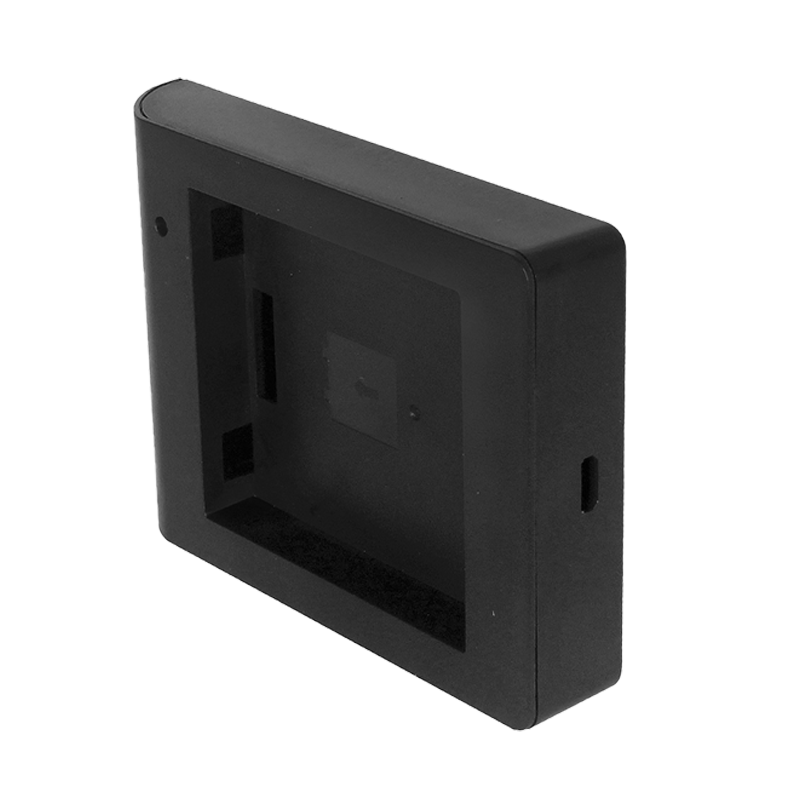
Instrument and device housings are a good example of where ejection design earns its keep. These parts typically combine thin outer walls, internal mounting bosses and a deep core, which is exactly the geometry that generates high normal pressure and vacuum. A layout that pins the boss rings and the stiffening ribs, adds air assist on the deepest section and keeps every mark on the hidden side will run for the life of the tool.
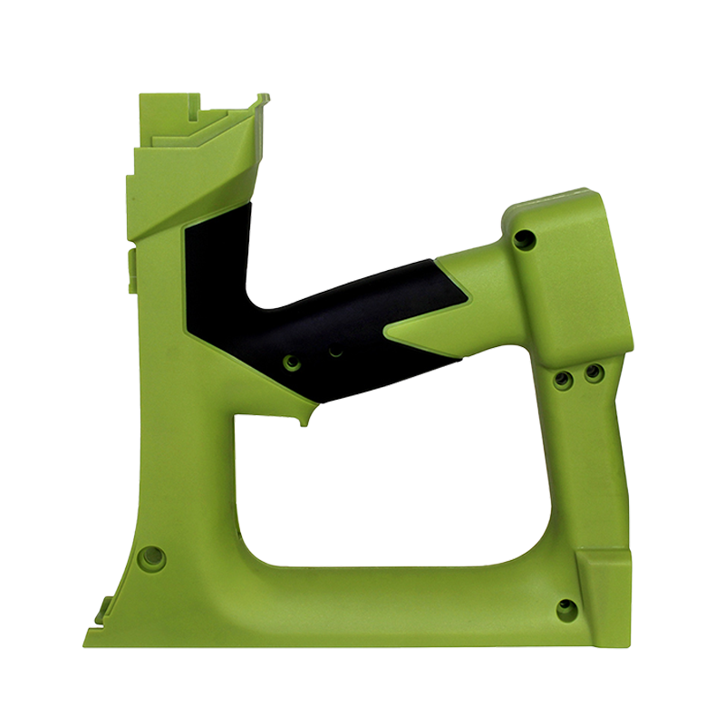
Power tool housings add a second challenge: thick walls, impact-modified resins and a strong pull on the core after packing. Here the priority shifts toward larger pin diameters, balanced placement around the motor bore and the handle, and pin materials that resist abrasion when glass-filled grades are used. Getting this right protects both the cosmetic surface and the pin life.
 Auto Parts AHow long can I get the feedbacks after we sent the inquiry? We will reply you within 12 hours in working day.View Product →
Automotive filter element frames and similar parts run at very high volumes, so tool maintenance economics dominate. Nitrided or coated pins, a documented replacement interval and a wear log are usually more valuable than any single design refinement, because a pin that survives two million shots instead of 400,000 changes the total cost of ownership considerably.
The company also supplies finished household plastic products to wholesalers and distributors alongside its custom moulding work, which means the same tooling discipline applies to products that must look consistent across very large production runs. For buyers comparing suppliers, the useful questions are always the same: how are pins sized, how is layout verified, what is the maintenance interval, and who signs off the cosmetic standard.
Related pages from our site
Maintenance, Wear Limits and Spare Pin Management
An ejection system that performs perfectly at 5,000 shots can be a source of scrap at 500,000. Wear is gradual and easy to overlook, especially when the operator compensates by nudging ejection speed or mold temperature. A simple maintenance routine catches almost all of it.
- Check pin protrusion across the full set every three to six months and re-set anything outside 0.05 mm of the target.
- Measure pin hole clearance or gauge the holes whenever flash appears around a pin.
- Inspect guide pins and bushings for the ejector plate; play here shows up as side load on pins.
- Look for polishing wear, galling or a bright band on pin shanks, which indicates friction inside the hole.
- Record the shot count at which each pin is replaced, and use the data to set a planned interval.
- Keep a spare set of pins in the two or three most common diameters used by the tool, cut to length in advance.
- Re-check plate flatness after any major repair, since plate distortion is often the real reason pins bend.
Pin life is resin-dependent. Unfilled polyolefins are gentle and pins can run for a very long time. Glass-filled polyamides, PBT and some mineral-filled grades act like a lapping compound and will wear both pins and holes. In those jobs, an interval of 300,000 to 500,000 shots for inspection is realistic, and a documented replacement plan avoids the situation where a single worn pin damages a hardened core insert.
Lubrication deserves a mention, because opinions differ. Many production molds run ejector systems dry, relying on close clearance and smooth finishes. Others use a high-temperature, non-migrating grease on the pin shanks. The deciding factor is usually the resin: any lubricant that can migrate into the cavity and contaminate the part is unacceptable for medical, food-contact or optical applications. When in doubt, keep the system dry, specify coated pins and maintain clearance carefully.
The ejector plate itself should be part of the inspection. A plate with worn guide bushings travels slightly off-square, which means pins enter their holes at a small angle and wear on one side. This is a slow failure that produces no obvious symptom until pins start snapping or parts start ejecting unevenly. Measuring plate squareness at each major service is cheap insurance.
What to Specify in an Ejector Pin RFQ
Most tooling disputes about ejection trace back to an RFQ that mentioned only the part, the resin and the annual volume. Supplying the right information up front costs nothing and eliminates most of the argument later.
- Provide the final 3D part model with wall thickness, rib and boss geometry, and any texture requirement including the texture specification and depth.
- State the cosmetic standard explicitly, including which surfaces may carry a pin mark and how large a mark is acceptable.
- Specify the resin grade, filler content and any colourant, because shrinkage pressure and abrasiveness both change with the compound.
- Give annual and lifetime volumes, so the supplier can justify nitrided or coated pins and a maintenance interval.
- Ask for a pin layout drawing as a deliverable, showing diameter, position and the surface each pin contacts.
- Request the total pin contact area and the calculated local contact pressure for the stated resin.
- Confirm the pin material, hardness and surface treatment for each pin size used in the tool.
- Ask for the ejection plate thickness, guide system and support pillar arrangement on tools with a large pin count.
- Agree the ejection stroke and the part clearance at full stroke.
- Define the maintenance interval and the wear criteria that will trigger pin replacement.
Two of these items cause most of the avoidable rework. The cosmetic standard is frequently left vague, which means the supplier designs for function and the buyer evaluates against an unstated visual expectation. Total contact pressure is rarely requested, yet it is the single number that predicts whether a part will whiten, dimple or release cleanly.
It is also worth asking how the supplier intends to validate the layout. A short mold flow study or a simple ejection force estimate costs little and often catches an undersized pin pattern before any steel is machined. Suppliers with in-house mold design and machining tend to answer this question with a process rather than a promise.
FAQ: Ejector Pins Injection Molding
How many ejector pins does a typical mold need?
There is no fixed number. Start from the part geometry: place pins under every major rib intersection, at each boss ring, at corners and along long side walls, then check that the total contact area keeps local pressure within the working limit for the resin. Most instrument and equipment housings end up with 8 to 20 pins, while a small sensor cap may need only two or three.
What diameter ejector pin should I use?
Use a pin at least as large as the local wall thickness, and around 80 percent of the rib width when pinning a rib. In practice, 3 mm to 6 mm pins cover most consumer, instrument and appliance parts. Larger diameters spread load better but consume more space on the core and require thicker ejector plates.
Why do ejector pins leave white marks on my parts?
White or silvery marks are stress whitening, which means the pin pressed harder than the polymer could carry at ejection temperature. The fix is to increase total contact area by adding pins or enlarging existing ones, confirm the part is fully cooled before ejection, and check that the pins sit on supported geometry rather than on a free panel.
Can ejector pin marks be eliminated completely?
On a functional part, marks can nearly always be hidden by moving pins to ribs, bosses or the non-cosmetic side. On a high-gloss visible surface, marks cannot be eliminated entirely with conventional pins; the alternatives are sleeve ejection, a stripper plate, air assist, or a texture that visually disguises the contact points.
What is the difference between through-hardened and nitrided ejector pins?
Through-hardened pins carry their hardness across the full section and are tough and economical, which suits unfilled resins and moderate volumes. Nitrided pins have a very hard surface case over a tougher core, which resists the abrasion caused by glass-filled and mineral-filled compounds but should not be ground through during fitting.
How much draft does a part need for reliable ejection?
As a working rule, 0.5 degrees per side is the minimum for shallow smooth walls, 1 degree is comfortable for general work, and 1.5 to 3 degrees is typical for deep walls or textured surfaces. Add roughly 1 degree of extra draft for every 0.025 mm of texture depth to prevent the texture itself from dragging.
Why does my part stick and then release with a loud pop?
That sound usually means vacuum. A deep, closed core pocket is sealed by the part, and the pins must overcome atmospheric pressure before they overcome friction. An air poppet valve, a vented core insert or a small ejector stroke combined with air blow-off will release the vacuum, reducing both noise and pin marks.
How often should ejector pins be inspected?
For unfilled polyolefins, an inspection every six months or every 500,000 shots is usually adequate. For glass-filled or abrasive resins, shorten that to every three months or 300,000 shots. Any appearance of flash around a pin hole calls for an immediate clearance check rather than waiting for the next scheduled service.
Can I run ejector pins without lubrication?
Yes, and many production tools do. Dry running depends on good clearance, smooth shank finishes and, in demanding jobs, a low-friction coating. Lubricants are sometimes used but must be evaluated against contamination risk, particularly for medical, food-contact and optical parts.
Does the ejector plate thickness really matter?
It does. A thin plate flexes under the combined load of many pins, which changes the effective stroke across the part and causes uneven ejection. Toolmakers typically add support pillars and increase plate thickness as pin count and pin diameter grow, and plate thickness should be reviewed whenever the pin layout changes.
Ejector pins injection molding rewards early decisions. The pins themselves are inexpensive, replaceable and well understood; what costs money is the layout that puts them in the wrong place, the missing draft that forces them to work harder than they should, and the deep sealed core that makes them fight a vacuum on every cycle. Review the pin layout while the geometry is still soft, keep local contact pressure inside the working range for the resin, and put the cosmetic standard in writing.
Do that and the ejection system becomes the quietest part of the tool: no whitening, no popping, no snapped pins, no arguments about whether a mark is a defect. If you are planning a housing, bracket or enclosure project and want the ejection design reviewed alongside the part and the mold, our engineering team can look at your model and outline a pin layout, the contact pressure figures and the material grade that fits your volume and resin.