English
 Español
 简体中文
Content
- 1 How to Create a Plastic Mold: The Manufacturing Workflow at a Glance
- 2 What Is a Plastic Mold and What Does It Actually Do?
- 3 Types of Plastic Molds and How to Choose the Structure
- 4 The Step-by-Step Mold Making Process from CAD to Mass Production
- 4.1 1. Review the Part Design for Manufacturability
- 4.2 2. Design the Mold in CAD
- 4.3 3. Select the Steel Grade and Procure Material
- 4.4 4. Rough Machining of the Mold Base and Blanks
- 4.5 5. Precision Machining of the Cavity and Core
- 4.6 6. EDM for Fine Details and Sharp Corners
- 4.7 7. Polishing, Texturing, and Coating Preparation
- 4.8 8. Assembly and Fitting of the Complete Mold
- 4.9 9. Trial Injection and Process Optimization
- 4.10 10. Dimensional Verification and Mass Production Approval
- 5 Choosing the Right Mold Steel
- 6 Part Design Considerations That Decide Mold Success
- 7 Application-Specific Mold Design and Manufacturing
- 8 Mold Cost, Lead Time, and Quality Control
- 9 DIY Mold Making vs. Working with a Professional Mold Manufacturer
- 10 How to Choose a Plastic Mold Manufacturer or Supplier
- 11 Conclusion and Mold Making Resources
How to Create a Plastic Mold: The Manufacturing Workflow at a Glance
An R&D engineer at an instrumentation company once asked us a deceptively simple question: how to create a plastic mold for a new sensor housing they wanted to launch within three months. There is no single workshop trick that answers that question. In short, you create a plastic mold by reviewing the part design for manufacturability, designing the mold structure in CAD, selecting the correct steel, machining the cavity and core, assembling and polishing the tool, running injection trials, and validating every critical dimension before mass production. Each of those stages determines whether the final parts are dimensionally stable, cosmetically acceptable, and economically viable at scale.
The answer matters because a mold is the most expensive single tool in the plastic parts supply chain. A poorly placed gate can leave visible sink marks on a high-gloss surface. A cavity without enough draft angle can scratch every part during ejection. A cooling layout with uneven channels can double your cycle time. An incorrectly chosen steel grade can crack after 20,000 shots. For a company that has created plastic molds for clients across instrumentation, industrial automation, automotive, lighting, kitchenware, medical devices, and IoT hardware since 1988, these failures are familiar; the solution is always the same set of engineering disciplines applied in order.
This guide explains how to create a plastic mold from the perspective of a plastic mold manufacturer and injection molding supplier. It covers the step-by-step process, mold types, steel selection, part design rules, cost and lead time, quality control, and the point at which you should involve a professional mold making partner instead of attempting a shortcut.
What Is a Plastic Mold and What Does It Actually Do?
A plastic mold is a hardened steel tool containing a machined cavity and a mating core. During each molding cycle, the mold closes under clamping force, molten plastic is injected through the sprue, runner, and gate into the cavity, and then the plastic is held under pressure while it cools and solidifies. When the mold opens, ejector pins push the solid part out, and the cycle starts again. A typical cycle lasts from 20 to 60 seconds depending on wall thickness, material, and cooling efficiency, which is why the design of the mold has a direct effect on unit cost.
Every production injection mold contains the same fundamental systems. The mold base is the standard framework that aligns and supports the working parts; it is usually made of pre-hardened steel and sourced from a reliable mold base supplier. The cavity and core are the two shaped blocks that define the geometry of the part: the cavity forms the external surfaces, and the core forms the internal surfaces. The runner and gate system delivers molten plastic from the machine nozzle to the cavity, and its layout largely determines filling balance and visible gate marks. The cooling system circulates water or oil through channels drilled in the cavity and core blocks to remove heat from each molded part. Finally, the ejection system uses pins, sleeves, or a stripper plate to release the cooled part from the core.
Understanding these systems matters because every decision in creating a plastic mold begins with thinking about the molding cycle, not just the static shape of the part. A mold engineer works toward a simultaneous set of targets: fill the cavity completely, cool it uniformly, eject it without damage, and repeat the cycle with minimal scrap. When those four targets are met, the mold becomes a reliable production asset that can run for hundreds of thousands of shots.
Types of Plastic Molds and How to Choose the Structure
Choosing the right mold structure is one of the first decisions in how to create a plastic mold that is profitable, because the structure controls tooling cost, cycle time, and scrap rate. The five structures below cover the majority of parts made for instruments, automotive components, lighting, and household products.
Two-Plate Mold
The most common structure with a single parting line. Simply constructed, low cost, and suitable for most housings and brackets.
Three-Plate Mold
Adds a second parting plane; the runner separates from the part automatically. Useful for round parts and strict cosmetic top surfaces.
Hot Runner Mold
The runner stays melted inside a heated manifold. No runner scrap; ideal for high-volume engineering plastics.
Family Mold
Several different parts from one product set share a single mold base. Low tooling investment when volumes are moderate.
Insert Mold
Metal nuts, pins, or contacts are loaded before each shot, creating plastic-metal hybrid components in one cycle.
For most instrument enclosures, sensor shells, and appliance parts with annual volumes below 500,000, a well-built two-plate or three-plate mold offers the best balance of cost and reliability. Two-plate molds keep the tooling budget low and the maintenance simple, and they are the structure we recommend when the gate position can be placed on a hidden or non-critical face. Three-plate molds become necessary when the gate must be located in the middle of the part, such as for round dial covers or large flat lighting bezels, but they add a small amount of cycle time and complexity.
Hot runner molds are reserved for high-volume programs, typically over 500,000 shots per year, where the cost of cold runner scrap would be substantial. Family molds are a sensible choice for a complete product set that ships together, such as a base and a lid, but volume differences between cavities must be managed carefully. Insert molds are common in automotive and electrical components where threaded inserts or contact pins must be positioned precisely.
The Step-by-Step Mold Making Process from CAD to Mass Production
The full process of creating a plastic mold involves ten clearly defined stages. Each stage has its own inputs, equipment, and acceptance criteria, and skipping any of them invites problems in trial injection or production.
1. Review the Part Design for Manufacturability
Before steel is cut, the mold engineer evaluates the customer part model against the basic rules of injection molding. Wall thickness should be as uniform as possible, typically 1.5 to 3.0 mm for common thermoplastics. Draft angles of at least 1 degree should be applied to vertical walls, and internal ribs should be 50 to 60 percent of the nominal wall thickness to avoid sink marks. This design review is the cheapest stage to change the part geometry, because a modification here costs nothing compared to re-cutting a hardened cavity.
2. Design the Mold in CAD
The mold designer creates the complete mold structure in 3D CAD: cavity layout, runner and gate positions, cooling channel layout, ejector system, and parting surfaces. For complex parts or engineering resins, mold flow analysis is used to predict filling behavior, weld line positions, and air traps. The deliverables are a dimensioned mold drawing, a bill of materials, and a cooling circuit layout showing inlet and outlet positions for the molding operator.
3. Select the Steel Grade and Procure Material
Standard mold steel such as P20 or 718H is appropriate for most production molds rated up to a few hundred thousand shots. For transparent parts, corrosive resins, or PVC, stainless mold steel grades like S136 or 2316 are used. For high-cavitation hot runner systems and molds with high thermal load, H13 offers better heat resistance. The selected blocks are cut to size, stress-relieved, and delivered to the machining workshop with a material certificate.
4. Rough Machining of the Mold Base and Blanks
The mold base and pocket plates are rough-milled on CNC machining centers to remove the bulk of the material. At this stage the goal is speed with a controlled allowance: each surface is left with 0.3 to 0.5 mm of stock for finishing. A workshop with more than 20 machining centers can plan roughing and finishing operations in parallel for different mold sets, which shortens overall lead time.
5. Precision Machining of the Cavity and Core
The cavity and core are finished with high-speed CNC milling to achieve final dimensions. Typical machining tolerance on cavity profiles is plus or minus 0.01 mm, with surface finishes of Ra 0.8 µm or better before polishing. For production molds used in mass supply, precision machining determines whether the molded parts will assemble, seal, and match in color across batches.
6. EDM for Fine Details and Sharp Corners
Electrical discharge machining is used for features that a milling cutter cannot reach, such as deep narrow ribs, sharp internal corners, and fine textures. A graphite or copper electrode is machined to the inverse of the feature, and the EDM machine erodes the steel with controlled electrical sparks. This step is particularly important for gear teeth, locking hooks, and logo engravings.
7. Polishing, Texturing, and Coating Preparation
The cavity surface is polished to the required cosmetic finish, from a standard SPI B-3 finish up to a mirror finish of Ra 0.05 µm for transparent parts. If the product requires a leather or fine texture, the cavity is texture-etched before finishing. For high-wear molds, a nitriding or PVD coating can be applied after polishing to extend tool life and reduce friction at the parting line.
8. Assembly and Fitting of the Complete Mold
All components are assembled into the mold base: cavity and core blocks, guides and bushes, ejector pins, cooling fittings, and limit switches. The fitter checks that the parting line closes with zero flash gap, the ejectors return smoothly, and the cooling channels have no leaks at rated pressure. This assembly stage reveals the quality of all previous steps, and it is where most tooling problems are found and corrected.
9. Trial Injection and Process Optimization
The mold is mounted in an injection molding machine, and a trial shot is run using the specified material. The process engineer adjusts melt temperature, injection speed, holding pressure, and cooling time to achieve complete filling without flash, sink marks, weld lines, or distortion. First-article samples are measured against the part drawing, and any deviations are corrected either by minor steel adjustments or by process settings.
10. Dimensional Verification and Mass Production Approval
The final step is a full measurement report of the first samples, covering critical dimensions, flatness, and appearance. Once the customer approves the samples, the mold is released for mass production. During production, the mold is maintained with scheduled cleaning, inspection of cooling channels, and replacement of ejector pins or wear parts.
Choosing the Right Mold Steel
The steel grade inside a plastic mold does more than give the tool strength; it controls wear resistance, polishability, corrosion behavior, and heat transfer. When we create a plastic mold for a client, we select steel based on four inputs: production volume, plastic material, required surface finish, and the presence of thin ribs or sharp corners that concentrate stress.
| Steel Grade | Typical Hardness (HRC) | Best For | Key Property |
|---|---|---|---|
| P20 | 28–32 | Prototype and low-volume molds | Excellent machinability |
| 718H | 33–38 | Standard production molds | Good balance of polishability and wear resistance |
| S136 | 48–52 | Transparent and corrosive-resin molds | Corrosion resistance, mirror polish |
| H13 | 44–52 | High-cavitation and hot runner molds | Heat resistance and toughness |
| NAK80 | 38–42 | Textured surfaces and fine detail | Uniform hardness, excellent polishability |
For a standard plastic mold producing ABS or PP parts, 718H is the most practical workhorse: it is pre-hardened, machines well, and polishes to a good cosmetic finish. When the part is a clear lens or a cover that sees constant moisture, S136 provides corrosion resistance and a mirror polish down to Ra 0.05 µm. When the mold runs glass-filled nylon or a high-cavitation hot runner system, H13 keeps edges from eroding under high melt temperature. NAK80 is preferred when the cavity must hold a uniform fine texture, such as a leather grain on a consumer electronic shell.
Steel choice also affects delivery time. Common grades like P20 and 718H are usually available from local stock, while imported stainless grades may add one to two weeks to the schedule. The mold quote should always state the steel grade and hardness, because substituting a softer steel after quoting is one of the hidden ways a mold price can look attractive at the start and fail in production.
Part Design Considerations That Decide Mold Success
Many mold problems are actually part design problems. The following rules are the minimum requirements for a part that can be molded efficiently and ejected reliably.
Draft Angles
Draft angle is the taper on vertical walls that allows the part to release from the cavity. Without 0.5 to 1 degree of draft on vertical walls, the part can be scratched or stuck during ejection. For textured surfaces, draft must be increased to 1.5 to 3 degrees because the texture anchors the plastic into the steel. Every additional degree of draft is free; omitting it is expensive.
Wall Thickness Uniformity
Uniform wall thickness, typically 1.5 to 3.0 mm for engineering thermoplastics, prevents sink marks, warpage, and voids. Transitions between thick and thin sections should be gradual, with generous radii at corners. If a thick boss or rib is unavoidable, the mold designer adds cored-out slots underneath to keep the local mass close to the nominal wall.
Shrinkage and Tolerances
Every thermoplastic shrinks as it cools, and the cavity dimension must be scaled up by the material's mold shrinkage rate. The table below lists the shrinkage ranges we use when calculating cavity sizes for common resins.
| Material | Mold Shrinkage (%) | Typical Wall Thickness (mm) |
|---|---|---|
| ABS | 0.4–0.7 | 1.5–3.0 |
| PP | 1.5–2.5 | 1.0–3.5 |
| PC | 0.5–0.7 | 1.5–3.5 |
| PA66 | 1.0–2.0 | 1.0–3.0 |
| PE | 1.5–3.0 | 1.0–3.0 |
Shrinkage is not a single number; it varies with wall thickness, gate location, and holding pressure. A professional mold supplier adjusts the cavity dimensions using a combination of published shrinkage data and practical experience with the same resin grade. For precision parts with tight tolerances, the mold designer also leaves 0.1 to 0.2 mm of steel for fine-tuning after the first trial, so that dimensions can be adjusted in the few thousandths of a millimeter range.
Gate Location and Weld Lines
Gate location determines where the plastic enters the cavity, and it controls the position of weld lines, flow marks, and gate vestiges. Gates are placed on hidden surfaces or at the thickest section of the part. If two flow fronts meet, a visible weld line forms; moving the gate or adding a flow deflector can relocate that line to a low-stress area.
Undercuts and Side Actions
Snap-fit hooks, side holes, and internal threads require side actions or lifters in the mold. Each side action adds moving parts and mold cost, so designers should orient undercuts so they can be formed without additional mechanisms. Rotating the part in CAD by a few degrees often eliminates an expensive side action.
Application-Specific Mold Design and Manufacturing
The same mold making process adapts to very different product requirements, and application experience reduces trial and error. Instrument housings, automotive components, smart hardware, lighting parts, and household products each shift the balance of design decisions.
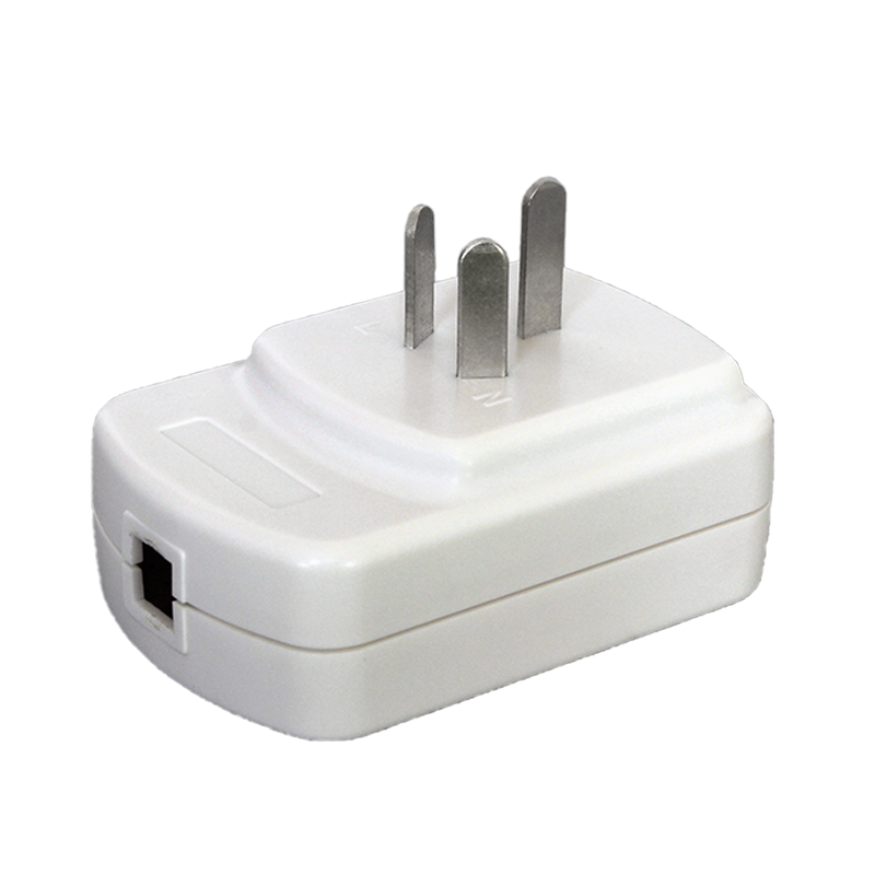
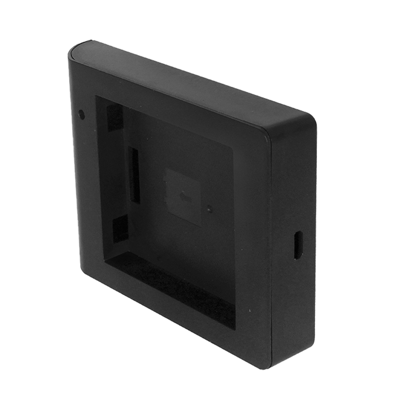
Instrument housings, detection accessories, and electrical enclosures usually demand tight dimensional control because the molded part must hold circuit boards, displays, and sealing surfaces. For these parts we create plastic molds with careful attention to gate position, to avoid flow marks on visible faces, and to ejection balance, so that thin-walled housings do not deform when released. A representative example is our custom instrument housing mold production, where the cavity is cut to tolerances around plus or minus 0.02 mm on critical mounting faces.
 Plastic Mold Casting Instrument Housing Maker, CompanyYuyao Hualong Moulds & Plastic Products Co.,Ltd is China Plastic injection molding Part Instrument Housing maker, company and service.View Product →
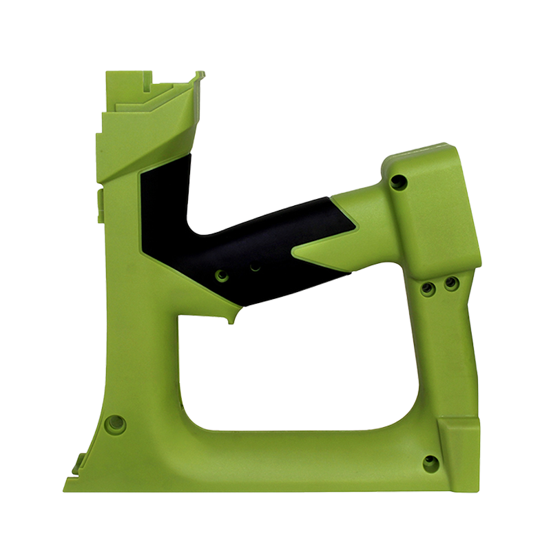
For automotive components such as radiator plastic parts, filter housings, and vehicle shells, the main concerns are heat resistance, vibration, and long production life. Mold cavities are typically hardened above 45 HRC, cooling channels are routed close to high-temperature areas, and sample validation includes temperature cycling. Material selection and shrinkage data become critical because many automotive grades are glass-filled and wear the mold faster.
Smart hardware products, including robot shells, robot dog covers, and consumer electronics bodies, combine cosmetic surfaces with snap-fits and internal structure in one part. A robot is often assembled from multiple molded shells that must match on parting lines and lock together without adhesive. In this case, creating a plastic mold for each shell as a linked family of tools, with consistent shrinkage prediction and identical gate style, is what makes final assembly possible. Our plastic robot shell molding services demonstrate how coordinated cavity design keeps assembly tolerances under control.
 Plastic Mold Casting Robot Maker, CompanyYuyao Hualong Moulds & Plastic Products Co.,Ltd is China Plastic injection molding Part Robot maker, company and service.The company is a...View Product →
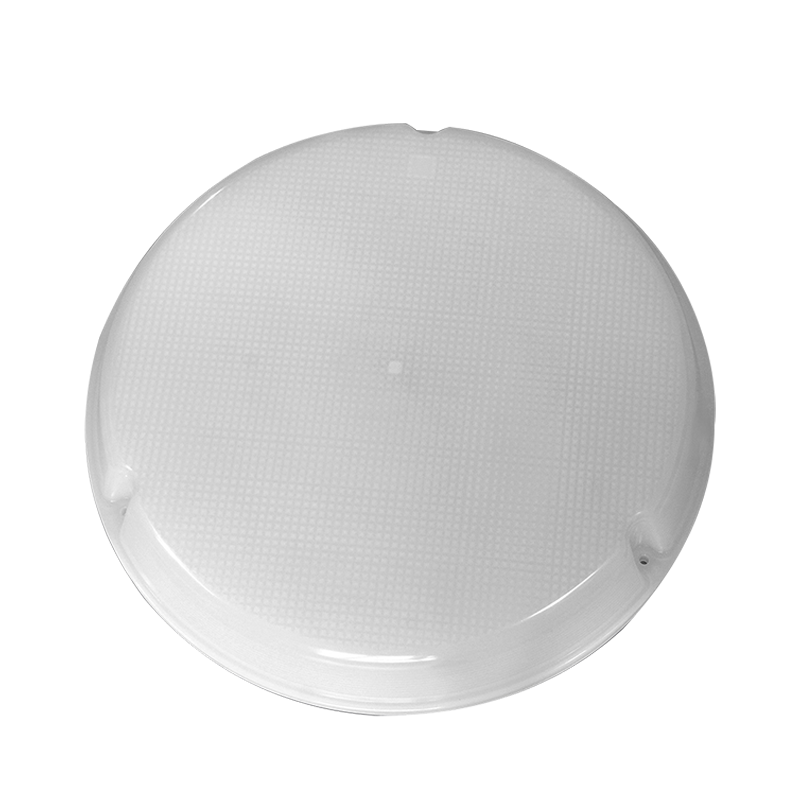
Lighting accessories such as plastic lampshades, baby lights, and wax-like plastic lamps are a separate discipline because the cavity surface finish directly controls light diffusion. A high-gloss polished cavity gives a transparent clear lens, while a fine matte texture creates a soft diffusion effect. Wall thickness must be controlled tightly to avoid bright or dark bands across the lit surface.
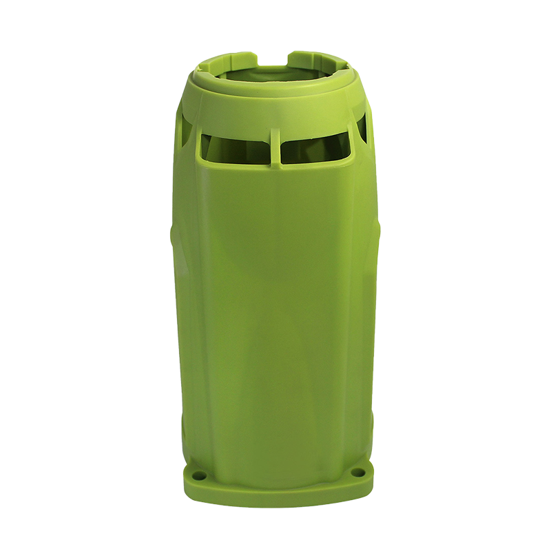
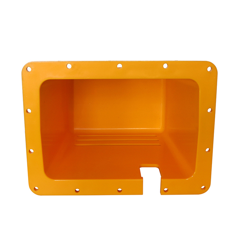
Household and kitchenware parts like peelers, mixers, water filter pots, and storage boxes are driven by cost per unit and surface appearance. The mold designer optimizes cavity count so that one molding cycle produces four or eight identical parts, lowering the unit price for the brand owner or wholesaler. Gate vestige and ejector witness marks are placed on non-visible surfaces because the retail customer handles these products every day.
Mold Cost, Lead Time, and Quality Control
Mold price and delivery time are the first commercial questions, and both depend on the same variables: part size, cavity count, mold structure, steel grade, and required finish. A simple two-plate mold for a small bracket can cost a few thousand US dollars, while a complex multi-cavity hot runner mold for an automotive component can exceed six figures. Lead time follows a similar curve. Buyers planning a new product launch should therefore build realistic expectations before the design phase ends. The chart below shows the typical lead time ranges we quote when a customer asks how to create a plastic mold for production.
A few observations from this chart are directly useful for planning. First, the shortest lead times are only possible when the part design is already finalized and the material is a common grade like ABS or PP. Second, the jump from a prototype mold to a production mold is about two to three weeks, which is small compared with the improvement in tool life. Third, multi-cavity molds save money per part but add machining time because every cavity must be cut and fitted individually. Fourth, hot runner molds require additional components, such as heated manifolds and controller wiring, so they take longer to commission. Fifth, the widest range, from ten to twelve weeks, usually applies to molds with deep ribs, fine textures, or tight tolerance requirements. A practical consequence is that launching a product with a rigid tooling deadline is risky; a one-week delay in design approval can shift the entire delivery. Another consequence is that buyers who need quick market entry should separate their tooling into a prototype stage and a production stage rather than waiting for the full production mold. The difference in total lead time is often only two to three weeks, but the risk is lower because the part can be tested in real applications. From a supplier perspective, these lead times are achievable only when mold design, machining, and trial injection are in the same building. That is exactly why our mold workshop and injection workshop operate under one roof, with 20-plus machining centers and injection machines ranging from 100 g to 3500 g of shot capacity. When machining and molding are separated, every trial shot requires shipping the mold, and that delay alone can add two to three weeks. Finally, prototype tools and production tools should be planned together so that design decisions made for the prototype mold, such as gate locations and ejection points, are transferable to the production mold.
Quality control runs through the entire mold making process rather than appearing only at final inspection. Our facility uses more than 20 inspection devices covering incoming steel hardness testing, in-process dimension checks, first-article measurement reports, and sample appearance evaluation. Each cavity is measured and recorded so the molding team knows the exact dimensional variation between cavities before production starts.
The main cost drivers for a plastic mold are easy to list and easy to underestimate.
- Part size: larger projected area requires a bigger mold base and a larger injection machine.
- Cavity count: more cavities multiply machining time and fitting effort.
- Mold structure: three-plate, hot runner, and side-action mechanisms add components and assembly work.
- Steel grade: stainless and hot-work grades cost more than standard P20 or 718H.
- Surface finish and texture: high-gloss polishing and chemical etching are labor-intensive.
- Tolerance requirements: tight tolerances demand slower machining and more inspection points.
- Delivery period: rushed schedules may require overtime and parallel machining.
DIY Mold Making vs. Working with a Professional Mold Manufacturer
The internet is full of tutorials showing how to create a plastic mold at home with silicone rubber and casting resin. These DIY approaches are valuable for validating shape and fit, but they are not the same as creating a plastic mold for production. The distinction is mostly about repeatability, tolerance, and volume.
DIY and Silicone Mold Methods
|
Professional Steel Injection Molds
|
When the business question is how many parts you need and what tolerance you need to hold, the answer selects the technology. For one-off prototype brackets, a 3D printed or silicone mold might be enough. For a batch of 10,000 identical housings that must assemble with a PCB, fit a mating cover, and survive drop testing, only a steel production mold makes financial sense. Professional mold shops also add value that DIY systems cannot easily match: mold flow analysis, experience with gate and weld-line control, insert molding, and a defined quality system for the injection process.
When production volume is in the tens of thousands or above, a custom plastic mold manufacturer is the correct partner. Our one-stop service model, from product development through molding and assembly, exists precisely for this situation: the customer brings a concept or a CAD file, and we handle mold design, machining, trial, mass production, and even final assembly. This model is especially attractive for importers and wholesalers who need a stable supply chain without managing separate tooling, molding, and assembly suppliers.
How to Choose a Plastic Mold Manufacturer or Supplier
Choosing the right mold maker is as important as the mold design itself. For buyers in North America, Europe, and other overseas markets, a reliable plastic mold manufacturer is one that can communicate clearly, meet your tolerance specifications, and deliver on the agreed schedule. Practical screening criteria include in-house mold making capability, injection molding capacity for trials and mass production, quality inspection equipment, experience in your product category, and the speed of design-for-manufacturability feedback.
A mold supplier that only builds molds but has no injection machines cannot validate the tool under production conditions. A molding factory that outsources the tooling loses control over quality and troubleshooting. A balanced manufacturer integrates both, as we do with injection machines ranging from 100 g to 3500 g, 20-plus machining centers, and a full set of inspection devices. The proof is in the first trial: a good supplier sends you a complete first-article report listing measured dimensions, photos, and recommended process parameters.
For products such as kitchen tools and daily-use articles, cavity count and runner balance are decided in the quoting stage, so choose a supplier that asks about your annual demand before quoting. Household accessories like plastic peeler mold manufacturing, storage boxes, and water filter housings are good examples of products where cavity-count optimization separates an average mold from a profitable one. If you plan to sell through wholesalers, that annual demand number matters even more, because it determines whether a four-cavity or eight-cavity mold is justified.
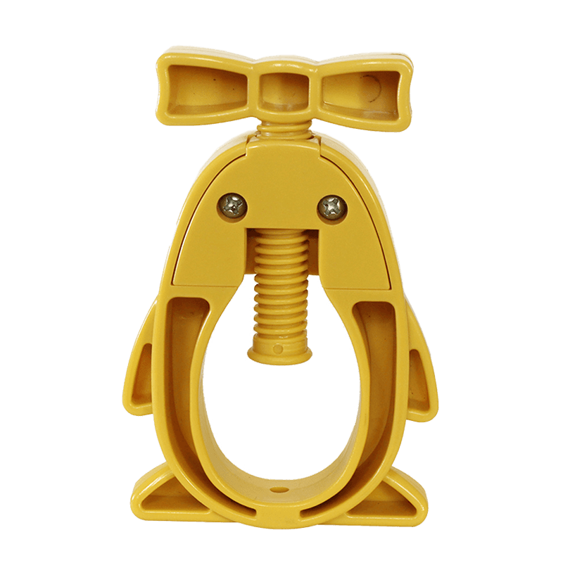 Custom Plastic Peeler Injection Molding Manufacturers, FactoryAs injection molded plastic Peeler manufacturers and factory in China, Yuyao Hualong Moulds & Plastic Products Co.,Ltd custom OEM/ODM PeelerView Product →
Conclusion and Mold Making Resources
Creating a plastic mold is a measurable engineering process: review the part for manufacturability, select the correct structure and steel, machine precisely, assemble carefully, and validate with trial shots. The mold that results is the most important asset in your plastic parts supply chain because it determines quality, cost, and delivery reliability for the entire product life. Whether you need a simple two-plate mold for a small housing or a complex multi-cavity tool for a mass-market product, the principles in this guide remain the same.
Plastic Mold Making Resources from Yuyao Hualong
If you are planning a new plastic product or improving an existing molded part, the following resources will help you start the conversation with the right technical information.
- Contact our mold design and injection molding team for a free design-for-manufacturability review
- One-stop service model: from product development to finished plastic parts
- Design guide for lighting accessories lampshade boards
Every custom plastic mold project starts with three questions: what is the part, what material will it use, and how many parts do you need per year. Send our engineering team a CAD file or a sample, and you will receive a DFM report, a mold layout proposal, and a delivery schedule before any steel is cut.